Figure 00.1 — The front panel. Every number on a diagram is tethered by a yellow line to the key beside it; click any figure to zoom it, and hover a number to read what it does.
How this guide works
Each section covers one part of the machine as a figure whose numbered call-outs are
tethered to a key naming every button, field and icon. Photographs are the real AutoSolder 6; the display
and dashboard drawings are faithful to the shipped firmware.
The three ways you drive it
Control
What it is
Use it to
Foot pedals
Two pedals on the floor
Run a solder cycle · feed extra wire — hands stay free (§06)
Panel buttons
UP · DOWN · SET
Read and change the five settings on the display (§02)
Web dashboard
Any phone or PC on the same Wi-Fi
Everything above, plus every machine parameter, tests and updates (§08–§14)
The machine ships locked. On first power-on it shows DEVICE LOCKED. Unlock it once — on the panel or in the browser — and it stays unlocked for good (§03).
Safety & warranty. This machine moves a motor-driven arm carrying a soldering iron at roughly 350 °C. Never put fingers under the iron while a pedal is connected; keep the area ventilated; switch off at the mains before opening the base; wash your hands after handling lead-bearing solder. Supplied as-is, without warranty of any kind; hjLabs.in is not liable for any loss, injury or damage arising from use.
Keep this page open while you learn the machine. Everything on it is explained in full later in the guide.
The panel buttons
Button
What it does
UP (red)
+0.25 on the shown setting · hold to run up fast
DOWN (green)
−0.25 · hold to run down fast
SET (blue)
Next menu page. Six pages, then back to the first
The foot pedals
Pedal
What it does
Pedal 1 — Cycle
Runs one complete solder cycle (§05). One press = one joint
Pedal 2 — Dispense
Feeds solder wire by hand — a chunk per tap, or continuously while held
Everything saves itself. Values you set on the panel or the web page are written to the machine's memory immediately and survive power-off.
The six display pages
#
Page
Range
1
Solder — wire fed per joint
0.25 – 100 mm
2
Time — iron dwell on the joint
0.25 – 10 s
3
Fan — cool-down after the joint
0 – 20 s
4
Type — Pre / Post / Manual
3 modes
5
Z-Hgt — how far the iron drops
0 – 50 mm
6
Network — address & Wi-Fi state
read-only
The three modes — at a glance
Mode
Order of events
Use it for
Pre
wire → down → dwell → up
Most through-hole work; the default
Post
down → wire → dwell → up
Pre-tinned pads, wire that must melt on a hot joint
Manual
down → you feed → up
Odd joints, learning a new board, rework
Common tasks
To…
Do this
Change how much solder
SET to Solder → UP / DOWN (§04)
Change the dwell
SET to Time → UP / DOWN (§04)
Set the drop depth
SET to Z-Hgt. 0 = drop until the limit switch (§04)
Switch mode
SET to Type → UP / DOWN (§05)
Find the web page
SET to Network → read the address (§07)
Feed wire by hand
Tap pedal 2 (§06)
Reset the counter
Dashboard → ↺ beside the number (§08)
Move it to new Wi-Fi
Dashboard ≋, or power-cycle 5× quickly (§07)
Before every session: check the iron tip is clean and tinned → check the wire runs freely off the spool → switch on and let the iron reach temperature → test one joint on a scrap board before you touch the real one.
If something looks wrong
You see…
Likely cause
What to do
Display reads DEVICE LOCKED
Machine not yet activated
Unlock it — panel code or web password (§03)
Pedal does nothing
Machine is locked, or pedal unplugged
Unlock (§03); check the pedal plug and the state pills (§08)
Display blank, machine still works
The display cable has come loose
It runs headless by design — reseat the display cable; it recovers on its own (§17)
Iron drops but never stops
Limit switch not tripping
The descent aborts itself after 20 s. Check both limit switches (§14)
Too much / too little solder
Solder Size wrong, or wire feed uncalibrated
Adjust Solder Size (§04); then calibrate pulses/mm (§13)
Feeder slips, wire does not move
Feed pressure or a jam in the guide tube
Clear the tube, check the drive pressure (§17)
Web page will not load
Machine not on your Wi-Fi
Read the Network page on the display (§07)
The wrong motor moves
Pin map does not match your wiring
Swap the Z / Dispense pins in GPIO mapping (§14)
Need a hand?
hjLabs.in support · +91 70165 25813 · [email protected] — quote your firmware version and what the display shows.
Keep it updated
New firmware installs over Wi-Fi from the dashboard — no cable, no programmer (§15).
Handle with care
The iron is hot long after power-off. Let it cool before moving or covering the machine.
6Work plate — the perforated bed your jig or board sits on
7Front panel — display and the three buttons — see §02
8Base enclosure — the controller, the motor drivers and the power supply live in here
9Wire guide tube — the spiral steel tube that carries the wire from the drive to the tip
10Column — the rigid backbone everything hangs from — never lean on it
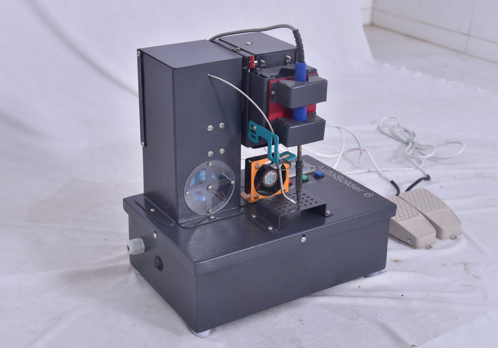
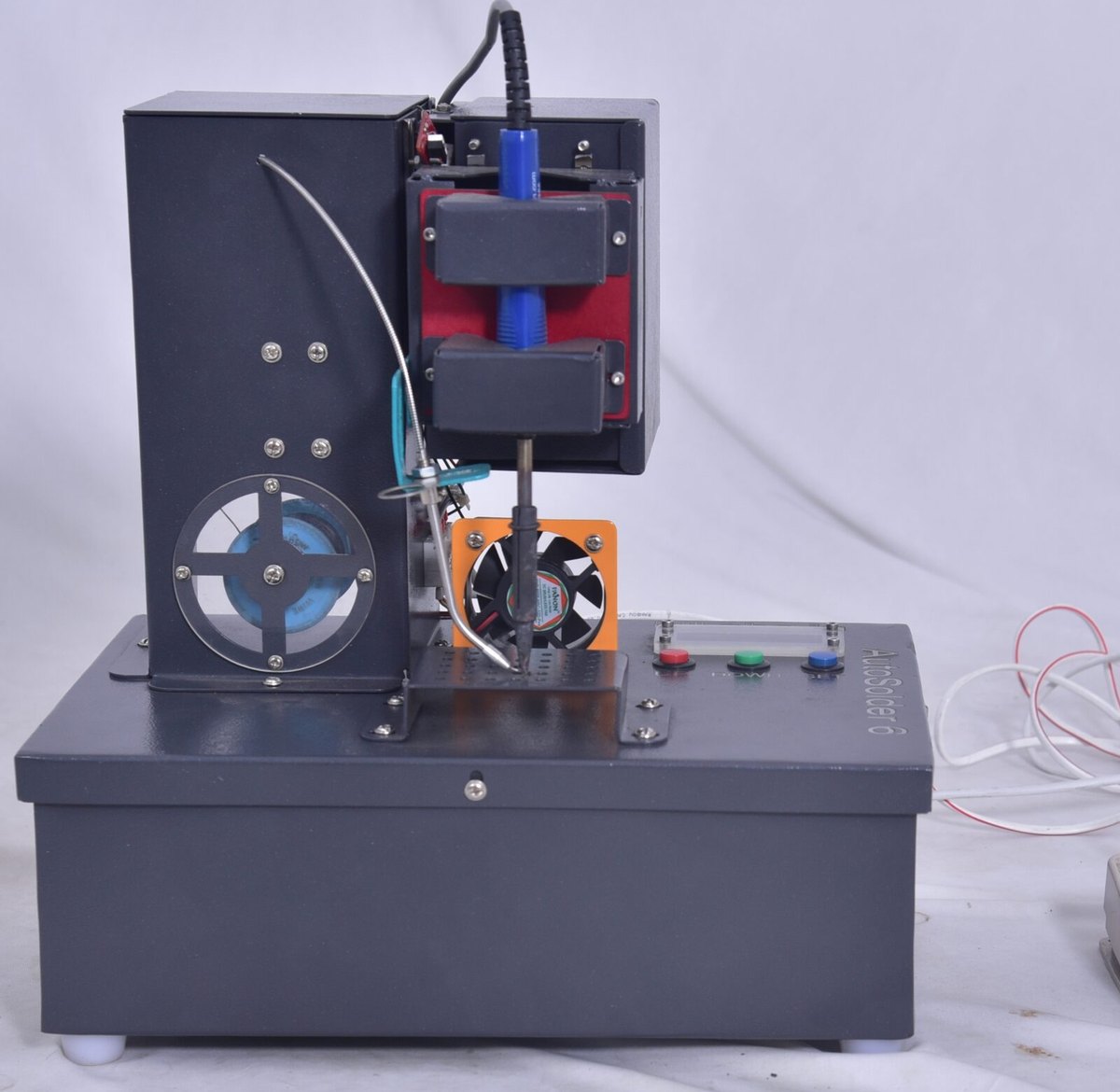
Figure 01.1 — AutoSolder 6, front view. The machine is a single rigid column: wire goes in at the top, the iron comes down at the bottom.
What is in the box
Item
Notes
AutoSolder 6
Assembled — column, feeder, Z axis, iron and fan on one base
Two foot pedals
Pedal 1 runs the cycle · pedal 2 feeds wire (§06)
Mains lead
Into the inlet on the side of the base
Soldering iron
Fitted, with a conical tip
This guide
Keep it with the machine
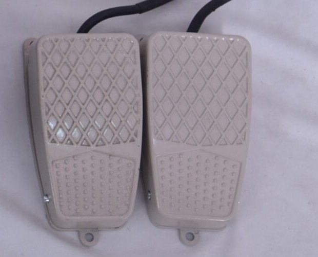
Figure 01.2 — The two pedals. Mark them; they are identical outside and do very different things (§06).
Setting it up — first power-on
Stand the machine on a flat, solid bench. It is heavy at the base by design — do not shim it.
Plug pedal 1 (cycle) and pedal 2 (dispense) into their sockets and lay the leads where nobody will trip.
Load the spool: feed the wire into the guide tube, through the drive, until about 5 mm sticks out past the tip.
Connect the mains lead and switch on at the rocker on the side of the base.
The display plays the hjLabs.in → AutoSolder 6 start-up animation, then shows either the settings
menu (§02) or DEVICE LOCKED (§03).
Let the iron come up to temperature, wipe the tip on a damp sponge and re-tin it.
Put a scrap board under the tip and press pedal 1 once. Adjust Solder Size and Time (§04) until the
joint looks right — then start work.
Never run a cycle with nothing under the tip. The iron will drive down to the limit switch and press hot metal against the work plate.
12
1Line 1 — the maker — hjLabs.in
2Line 2 — the product. Seeing both means the controller booted and the display is healthy
Figure 01.3 — The start-up screen, about three seconds after switch-on.
No start-up screen but the pedal still works? The display has come loose on its cable. The machine deliberately keeps running without it and re-connects the display by itself once the cable is reseated (§17).
hjLabs.in · AutoSolder 6 Operator's Manual§01 The machine · 04
AutoSolder 6 · User Guide · v6.0
02 · Panel & display
The panel, the display & the six pages
Three buttons and sixteen characters by two lines are all you need for day-to-day work. This is how to read them.
Reading the display
12345
1Selector — the solid arrow marks the line you are editing — UP / DOWN act on this line only
2Setting name — shortened to fit sixteen characters: Solder · Time · Fan · Type · Z-Hgt
3Value & unit — the live value; changes the instant you press a button and is saved straight away
4No arrow — line 2 is only a preview of the next page — it cannot be edited from here
5Next page — press SET and this line moves up to become the editable one
Figure 02.1 — The settings display. Sixteen characters by two lines, exactly as the machine draws it.
The three buttons
Button
Tap
Hold
UP
+0.25 (or next mode)
Runs up continuously after 1 s
DOWN
−0.25 (or previous mode)
Runs down continuously after 1 s
SET
Next page
— nothing extra
SET never changes a value and there is no “save” button. Whatever the display shows is what the machine will do on the next pedal press.
The six pages, in SET order
#
Shows
Meaning
Limits
1
Solder:5.0mm
Wire fed per joint
0.25 – 100
2
Time:10.0s
Iron dwell on the joint
0.25 – 10
3
Fan:15.0s
Cool-down after the joint
0 – 20
4
Type:Pre
Pre · Post · Manual
3 modes
5
Z-Hgt:0.0mm
Iron drop depth · 0 = auto
0 – 50
6
Network
Address & Wi-Fi state
read-only
Press SET six times and you are back where you started. The machine
always powers up on page 1 showing the values you last used.
A new AutoSolder 6 arrives locked. Two minutes of one-time setup and it is yours for good.
Why it is locked
Every AutoSolder 6 leaves hjLabs.in locked to the controller inside it. Unlocking is a
one-time step that ties the machine to its own hardware; after it, the machine powers up straight into the
settings menu forever. Nothing you do later — factory reset, firmware update, new Wi-Fi — will lock it again.
123
1Spark icon — a status screen, not a setting
2The state — the controller will refuse every pedal press, every button and every web command until unlocked
3Scrolling help — the full text runs past: “Unlock on the web page (join Wi-Fi, enter password), OR press UP/DOWN here to key in the unlock code then SET.”
Figure 03.1 — The locked screen, shown from the moment the start-up animation ends.
While locked, the machine is inert. Pedals do nothing, the settings cannot be changed, and every web command that would move a motor answers 403 Device locked. This is deliberate.
Way 1 — unlock on the machine
1234
1Prompt — you are in code-entry mode — reached by pressing UP or DOWN on the locked screen
2Digit counter — which of the eight digits you are on
3The code — eight digits, all starting at 0
4Blinking digit — UP counts it 0…9 and wraps · DOWN counts back · SET confirms it and moves right
Figure 03.2 — Keying the unlock code in on the machine itself. No network needed.
On the locked screen, press UP or DOWN once. The code-entry screen appears.
Set the first digit with UP / DOWN, then press SET to move to the next.
After the eighth digit, SET checks the code.
Right code → ✦ Unlocked! / Welcome - AutoSolder 6, then the menu.
Wrong code → Wrong code and it clears back to eight zeros — try again, there is no lock-out.
Your eight-digit unlock code is supplied with the machine, on the delivery note. It is not printed in this guide and never shown on the display.
Way 2 — unlock in the browser
Get the machine onto your Wi-Fi and open its page — see §07. This works even while it is locked; the
dashboard is readable, just not usable.
A full-screen Device Locked panel covers the page with one password box.
Type the activation password supplied with the machine and press Activate.
The page reloads unlocked, and the display drops straight into the settings menu.
The activation password (web) and the eight-digit code (panel) are two different secrets for the same lock. Either one unlocks the machine permanently; you never need both.
Symptom
What it means
Do this
Display shows DEVICE LOCKED
Never activated, or a replacement controller was fitted
Unlock by either route above
Web page greys out behind a lock panel
Same — the machine is locked
Enter the activation password
403 Device locked from a script
An API call was made while locked
Unlock first, then retry (§16)
Code refused every time
Wrong code, or digits confirmed out of order
Start again; the counter shows which digit you are on
Locked again after an update
Should not happen
Contact hjLabs.in with your machine's MAC address (§17)
Keep it safe
Write the unlock code and activation password somewhere your workshop can find them — a replacement controller needs them again.
Solder, Time, Fan, Type and Z-Hgt are the whole language of the machine. Learn these five and you can solder anything it can reach.
1 · Solder Size
2 · Solder Time
3 · Fan Time
4 · Type / Mode
5 · Z Height
Figure 04.1 — The five editable pages, in the order SET visits them.
Line 2 always previews what comes next.
What each one actually does
Setting
Physically
Range · step
Turn it up when…
Turn it down when…
Solder Solder Size
Millimetres of wire the feeder pushes out for this joint. This is length of wire, not a volume — a thicker wire at the same setting puts far more metal on the pad.
0.25 – 100 mm 0.25 mm
The joint is starved — a dull, concave fillet that does not wet the pad
You get a blob, a bridge to the next pad, or a spike
Time Solder Time
Seconds the iron stays pressed on the joint after it arrives. The display draws a progress bar for exactly this long.
0.25 – 10 s 0.25 s
The solder does not flow and stays grainy — heavy copper or a ground plane needs longer
Pads lift, plastic parts soften, or the tip burns the board
Fan Fan Time
Seconds the cooling fan runs after the iron lifts. 0 switches the fan off entirely.
0 – 20 s 0.25 s
You want the joint solid before the board moves, or you are clearing fume faster
You are chasing cycle time and the joint is small
Type Mode
Which of the three cycles runs on a pedal press — Pre, Post or Manual. Explained in full in §05.
3 modes
—
—
Z-Hgt Z Height
How far the iron travels down. 0 = automatic: it descends until a limit switch trips, which is right for almost every job. Any other value is a fixed depth in millimetres.
0 – 50 mm 0.25 mm
The tip is stopping short of a recessed joint (fixed-depth mode)
The tip is pressing too hard — or set it back to 0 and let the switch decide
Z Height — the one to understand
Leave it at 0 unless you have a reason not to. At 0 the iron simply drives down until the
spring-loaded head or the lead-screw switch says “I have touched something”, so every board thickness and every
jig height is handled automatically, and the tip lands with the same gentle pressure each time.
Give it a number and the machine counts millimetres instead. That is useful
when the joint sits down inside a recess the head cannot reach, or when you deliberately want the tip to stop
just above the work. It is also the setting that can drive the tip into the board if you get it wrong, so
test it on scrap.
The 20-second rule. In automatic mode, if no limit switch trips within twenty seconds the machine stops the descent by itself and prints a warning. If you see the iron creep all the way down and then stop, a limit switch is not being reached — see §14.
A worked starting point
Job
Solder
Time
Fan
Mode
Z-Hgt
Ordinary through-hole pin, 1.6 mm FR4
5.0 mm
1.5 s
2 s
Pre
0
Heavy pad on a ground plane
7.5 mm
3.0 s
3 s
Pre
0
Pre-tinned pad / wire to terminal
3.0 mm
2.0 s
2 s
Post
0
Unfamiliar board, first article
—
2.0 s
2 s
Manual
0
These are starting points, not specifications — wire diameter, alloy, tip
shape and iron temperature all move them. Change one setting at a time and run a test joint after each.
Every change takes effect on the very next pedal press. There is no confirm step and no undo. If you are unsure what you just changed, press SET around to the page and read the value back.
Reading the joint — what it is telling you to change
The joint looks like
It means
Change this
Which way
A smooth, shiny cone that wets the pad and climbs the lead
Correct. Leave it alone
—
—
Dull, grainy, sitting on the pad rather than wetting it
Not enough heat, or a dirty tip
Time — after wiping and re-tinning
Up, 0.25 s at a time
Thin and concave, the lead visible through it
Not enough solder
Solder
Up, 0.5 mm at a time
A ball that hides the lead, or a bridge to the next pad
Too much solder
Solder
Down
A spike or tail as the tip lifts
Still molten when the iron left
Time, then Solder
Time up, Solder down
The pad lifted, or the board is scorched
Far too much heat
Time
Down; check the iron's own temperature
Change one setting, make one joint, look at it. When several in a row are
right, note the numbers on the machine record at the end of §17 — that is your recipe for that board.
hjLabs.in · AutoSolder 6 Operator's Manual§04 The five settings · 07
AutoSolder 6 · User Guide · v6.0
05 · Pre · Post · Manual
The three solder cycles
Pre, Post and Manual differ in one thing only — when the wire is fed. Pick the one that suits the joint.
Every cycle, in one picture
One press of pedal 1 runs one complete cycle. What changes between the modes is
when the wire is fed — everything else is the same.
PRE — Type:Pre — the default
POST — Type:Post
MANUAL — Type:Manual
Figure 05.1 — The three cycles. The fan step is skipped
entirely when Fan Time is 0.
Which mode, and why
Mode
What happens
Choose it when
Pre
The feeder pushes Solder Size millimetres of wire out before the iron comes down. The tip arrives onto wire that is already sitting on the pad, melts it, holds for Time, then lifts.
This is the normal mode. Wire and heat arrive together, so the flux is fresh and the joint wets fast. Use it for ordinary through-hole work.
Post
The iron comes down first and heats the joint, then the feeder pushes the wire into the already-hot pad, then it holds for Time and lifts.
The pad is pre-tinned, or heavy enough that cold wire would just sit there. Also better when the wire would roll off a curved surface.
Manual
The iron comes down and stays down while you keep pedal 1 pressed. Every tap of pedal 2 feeds one Solder Size of wire. Release pedal 1 and the iron lifts.
Rework, odd geometry, an unfamiliar board, or when you are dialling a job in and want to watch the joint form.
Solder Size means the same thing in all three modes — the length of wire fed in one shot. In Manual mode it is fed per tap of pedal 2, so three taps deposit three times as much.
What the machine does, step by step
#
Step
Governed by
1
Display switches to ◆ Auto Cycle
—
2
Pre only: the feeder pushes wire
Solder Size · feed speed (§11)
3
The Z axis drives down
Z-Hgt, or the limit switches at 0 · travel speed (§12)
4
Post only: the feeder pushes wire now
Solder Size
5
Manual only: holds down while pedal 1 is pressed; pedal 2 feeds
you
6
Dwell — progress bar on the display
Solder Time
7
The Z axis returns up exactly the distance it came down
measured, not guessed
8
The fan runs, with its own progress bar
Fan Time · skipped if 0
9
The solder-point counter increments by one
§08
10
The settings menu comes back
—
Step 7 is worth knowing about: the controller counts the steps it took on the way down and
returns exactly that many. It never assumes a height. That is why the machine handles a stack of boards of
different thicknesses without being told, and why you should not push on the head while it is moving.
Manual mode holds the iron on the joint for as long as you hold the pedal. There is no dwell timer protecting the board — it is entirely on you. Lift your foot the moment the joint flows.
Trying a mode out
Change Type on the display (§04) and press pedal 1 on a scrap board. There is nothing else to configure.
Testing without the pedal
The dashboard's Move Iron button runs the same cycle from the browser (§08).
Feeding without a cycle
Dispense Solder, or a tap of pedal 2, feeds wire with no motion at all (§06).
Pre or Post? — the deciding question
Ask: would the wire stay where I put it, on a cold pad?
Yes — a flat pad, a hole with a lead in it, anything that traps the wire. Use Pre: the wire is
already in place when the heat arrives, so the flux is fresh at the moment it is needed.
No — a curved terminal, a vertical face, a pad the wire would roll off. Use Post. The tip goes
down first and holds the joint; the wire is then fed into a surface that is already hot and already tinned.
Not sure — use Manual for the first few, watch where the solder wants to go, then commit.
Post costs a little time. The pad has to come up to temperature before the wire arrives, so a Post joint usually needs a slightly longer Time than the same joint in Pre.
What the display shows, moment by moment
You see
The machine is
Roughly
◆ Auto Cycle
Starting — feeding wire (Pre) or about to descend
< 1 s
✦ Soldering + bar
Holding the tip on the joint
exactly Solder Time
◆ Manual - hold
Waiting for you — Manual mode only
while you hold pedal 1
✦ Cooling Fan + bar
Back up, and running the fan
exactly Fan Time
The settings menu
Finished — the counter has gone up by one
—
If the display sticks on ◆ Auto Cycle and the head keeps creeping down, no limit switch is being reached. The machine will stop itself after twenty seconds — then go and test the switches (§14).
hjLabs.in · AutoSolder 6 Operator's Manual§05 The three modes · 08
AutoSolder 6 · User Guide · v6.0
06 · The foot pedals
The foot pedals & running real work
Both hands stay on the board. Pedal 1 makes a joint; pedal 2 gives you wire. That is the whole workflow.
2Pedal 2 — Dispense — feeds solder wire on its own, with no machine motion at all
Figure 06.1 — The pedals do very different things and look identical. Label them on day one.
Pedal 1 — running a joint
Hold the board or jig in position under the tip with both hands.
Press pedal 1 once and let it go (except in Manual mode, where you hold it).
Watch the display: ◆ Auto Cycle → ✦ Soldering bar
→ ✦ Cooling Fan bar → back to the menu.
The iron is back up and the counter has gone up by one. Move to the next joint.
Pressing again mid-cycle does nothing. The controller is busy running the motors and only looks at the pedal between cycles — you cannot double-trigger a joint.
Pedal 2 — feeding wire by hand
Every tap pushes one chunk of wire out of the tip — by default 2 mm, set in
Machine Settings (§12). The iron does not move. Use it to prime a fresh spool, to add a touch of solder to
a joint that came out light, or as the wire supply in Manual mode.
Pedal behaviour
One tap
Held down
Continuous(factory default)
One chunk
Keeps feeding, chunk after chunk, from about half a second in — until you lift your foot
Fixed chunk
One chunk
Still exactly one chunk. Holding does nothing
Switch between the two in Machine Settings → Solder Pedal (§12).
Fixed-chunk is the safer choice for repeatable work; continuous is faster for loading a new spool.
Priming a new spool feeds a lot of wire. Hold pedal 2 with the tip over a bin, not over the board.
The solder-point counter
Every completed cycle — down, dwell, up — adds one to a counter stored in the machine's flash. It
survives power-off, is shown large on the dashboard (§08), and you can set it to any number or reset it to zero
from there. Feeding wire with pedal 2 does not count; nor do the Test buttons.
Per-shift output
Note the number at the start and end of a shift — the difference is joints made.
Tip life
Tips are usually specified in thousands of joints. The counter is how you actually know.
Pedal trouble
Symptom
Likely cause
What to do
Neither pedal does anything
The machine is locked
Unlock it (§03) — the display will be showing DEVICE LOCKED
Pedal 1 does nothing, pedal 2 works
Pedal 1 unplugged, or its lead is broken
Open the dashboard and press each pedal while watching the Pedal Up/Dn state pill (§08) — it should light
A cycle starts on its own
A stuck pedal, or the leads are swapped into the wrong sockets
Unplug both pedals; if it stops, the pedal is at fault
Pedal 2 feeds continuously
Pedal behaviour is set to Continuous and the pedal is sticking
Switch to Fixed chunk in Machine Settings (§12) to confirm, then replace the pedal
Both pedals do the same thing
The two leads are in the same socket group
Check the pin map — Pedal Up/Down and Pedal Dispense must be on different GPIOs (§14)
Setting the bench up for a shift
Pedal 1 under your stronger foot, pedal 2 under the other. You will press pedal 1 hundreds of times a
day and pedal 2 only occasionally.
Mark them. A stripe of tape on pedal 1 is enough. Reaching for the wrong pedal mid-run costs a joint.
Dress the leads along the bench leg, not across the floor where a chair will roll over them. Pedal
leads are the commonest failure on any machine like this.
Sit square to the machine — both hands should reach the work plate without leaning.
Keep the sponge and a spare tip within reach, so wiping is a reflex and not an interruption.
Rhythm — what a good run feels like
Step
You
The machine
1
Place the board, both hands
Idle, showing the settings
2
Press pedal 1 and release
Runs the whole cycle (§05)
3
Move to the next joint while the fan runs
Cooling
4
Press again
Next joint
Step 3 is where the time goes. Setting Fan Time to the length of time
it actually takes you to reposition — rather than a round number — is usually worth more than any speed setting
on the machine (§10, §12).
The counter is your stopwatch. Note it at the start and end of an hour; the difference is your real joints-per-hour, including everything that slowed you down (§08).
The machine hosts its own web page. Get it onto your network once and every browser in the workshop can reach it.
Getting it onto your Wi-Fi
Press SET around to page 6, Network. If it says Network Setup, the machine has no network yet.
On a phone or laptop, join the temporary hotspot the machine broadcasts: AutoConnectAP.
A setup page opens by itself (if not, browse to 192.168.4.1).
Pick your workshop Wi-Fi from the list, type its password, save.
The machine restarts, joins, and page 6 changes to Network Online with an address.
Type that address into any browser on the same network. The dashboard opens (§08).
12
1Not joined — the machine has no Wi-Fi credentials yet, or the network it knew has gone
2The instruction — scrolls: “Join WiFi 'AutoConnectAP' to configure this device”
Figure 07.1 — Page 6 before the machine has a network.
2.4 GHz only. The controller cannot see 5 GHz networks. If your router publishes both under one name, that is fine — it will join the 2.4 GHz half.
Its two addresses
12
1Joined — the machine is on your Wi-Fi and serving its dashboard
2Its address — scrolls the friendly name then the IP — e.g. http://autosolder6-brisk-otter.local - IP 192.168.1.42
Figure 07.2 — Page 6 once it is on the network. Type either address into a browser.
Address
Looks like
Notes
Friendly name
autosolder6-brisk-otter.local
Never changes for this machine — it is derived from the controller's own hardware address. Two AutoSolder 6s on one network always get different names.
IP address
192.168.1.42
Handed out by your router and may change when it restarts. Fine for a quick look, poor for a bookmark.
Bookmark the .local name, not the IP. If .local will not resolve on your PC (some Windows setups), use the IP from page 6.
Moving the machine to a different network
Way 1 · from the dashboard
Open the dashboard and press the ≋ Wi-Fi button in the header, then Reconfigure Wi-Fi
and confirm. The machine forgets the old network, restarts and brings the AutoConnectAP
hotspot back up. Join it and pick the new network.
Way 2 · with the power switch
No dashboard reachable? Switch the machine off and on five times in quick succession, each
within about eight seconds of the last. The display counts the presses for you. On the fifth it shows
✦ WiFi Cleared and reboots into setup mode.
This is the escape hatch for a machine that moved workshop and can no longer see the Wi-Fi it knew.
Wi-Fi is optional
AutoSolder 6 solders perfectly with no network at all. The display and the pedals do everything
needed for production. Wi-Fi buys you the dashboard: calibration, hardware tests, backups, firmware updates and
the HTTP API.
Put the machine on your workshop network, not a guest network. Guest networks usually block devices from talking to each other, so the dashboard will not open.
Problem
Cause
Fix
Page 6 still says Network Setup after setup
Wrong password, or a 5 GHz-only network
Repeat the setup; watch for a typo in the password
AutoConnectAP hotspot never appears
The machine already has credentials
Clear them: five quick power-cycles, or the dashboard button
Address in the browser times out
Your PC is on a different network or VLAN
Same Wi-Fi, same subnet. Try the IP address from page 6
.local name not found
mDNS is not resolving on your PC
Use the IP address instead
Dashboard loads then stalls
Weak signal at the bench
Move the machine or add an access point — steel enclosures are unkind to Wi-Fi
14Dispense Solder — feeds a burst of wire — five times the Solder Size — with no motion at all
Figure 08.1 — The dashboard as it opens. Everything on the display is here, plus the counter, the live input states, per-setting hardware tests and the two speeds.
7Slider — drag for a feel of the range; it and the number are always the same value
8Range — the firmware's hard limits — you cannot type past them
Figure 08.2 — One card, enlarged. All seven cards work the same way.
The seven cards on the home page
Card
Unit
Range
On the display too?
What it changes
Solder Size
mm
0.25 – 100
Yes — page 1
Length of wire fed per joint (§04)
Solder Time
s
0.25 – 10
Yes — page 2
How long the iron dwells on the joint (§04)
Fan Time
s
0 – 20
Yes — page 3
Cool-down after the joint; 0 = fan off (§04)
Mode
—
Pre/Post/Manual
Yes — page 4
Which cycle runs on a pedal press (§05)
Z Height
mm
0 – 50
Yes — page 5
Drop depth; 0 = down to the limit switch (§04)
Feed Speed
mm/s
0.5 – 50
No
How fast wire leaves the tip — the same parameter as Feed speed in Machine Settings (§10)
Travel Speed
mm/s
1 – 200
No
How fast the iron rises and falls — the same as Travel speed (§12)
The three live regions
Region
Refreshes
What it tells you
Counter
Continuously
Completed cycles, stored in flash. Click the number to set it; ↺ to zero it (§06)
State pills
Continuously
Both pedals and both limit switches as they are right now — the fastest fault-finding tool on the machine (§14)
Card values
On load & save
What the machine will actually do on the next pedal press
Because the counter and the pills are polled from the machine, several people can have the page open at once and all see the same numbers. The page is served by the machine — it works with no internet connection at all.
The two action buttons
Button
Equivalent to
Notes
Move Iron
One press of pedal 1
Runs the complete cycle in the current mode — feed, down, dwell, up, fan — and counts as a solder point
Dispense Solder
A long hold of pedal 2
Feeds five times the Solder Size in one burst. Nothing moves; the counter does not change
Move Iron and every Test ▶ drive the real machine immediately, with no countdown and no confirmation. Check that nothing — and nobody — is under the tip before you press one.
hjLabs.in · AutoSolder 6 Operator's Manual§08 The dashboard · 11
AutoSolder 6 · User Guide · v6.0
09 · Dashboard tools
The dashboard's tools — every panel behind the header
Six buttons in the header open the rest of the web interface: Wi-Fi, machine parameters, backup, restore, the API reference and firmware.
Figure 09.1 — The header: six buttons, six panels. This strip is the whole of the web interface beyond the home page.
What is behind each button
Button
Panel
You go there to…
Needs unlocking?
≋ Wi-Fi
Its own page, at /wifi
See the machine's address, and press Reconfigure Wi-Fi to send it back to setup mode for a different network (§07)
To reconfigure
≡ Machine Settings
A large panel in two halves
Top: every machine parameter (§10–§12). Bottom: the GPIO pin map and the hardware self-tests (§14)
To save
↓ Export
An immediate download
Saves autosolder6-config.json — settings, parameters and pin map (§15)
No
↑ Import
A file-chooser dialog
Push a saved configuration back, or onto a second identical machine (§15)
Yes
▤ API docs
A reference panel
Every HTTP endpoint, with a copy button that fills in this machine's address (§16)
No
↻ Firmware
Upload + progress bar
Flash a new build over Wi-Fi — no cable, no programmer (§15)
Back up first
Figure 09.2 — Firmware Update. Choose a .bin, press
Upload & Flash. The machine reboots by itself at 100 % (§15).
Figure 09.3 — Import Config. Everything in the file replaces what is on the
machine — the pin map included (§15).
Figure 09.4 — The lock overlay covers the whole page until a never-activated machine is
unlocked (§03).
Things the interface does quietly
Behaviour
What you will notice
Splash screen
A one-off hjLabs.in → AutoSolder 6 animation while the page loads. It fades by itself
Toast messages
A dark bar slides up from the bottom to confirm a save, a test or an error
Works offline
Layout, panels and scripts are all served by the machine — only the icon font comes from the internet, with a plain-text fallback
No login
Beyond the activation lock there is no user account — anyone who can reach the machine can drive it (§16)
Immediate effect
Saving on the web page updates the physical display in the same instant, and it clamps out-of-range values rather than accepting them (§14)
Using the interface safely
Export before you change anything structural — one click now, no re-calibration later (§15).
Change one parameter at a time, then run a test joint.
Test ▶ before Save — the test buttons use the value in the box, saved or not (§13).
Keep the machine off the internet, and off a shared PC where somebody might lean on Move Iron.
Factory Reset (all) lives at the bottom of Machine Settings. It restores the five settings, every calibration value and the whole pin map in one press. Your counter and your unlock survive it, but nothing else does.
Two machines, one setup
Commission machine 1 properly, Export, then Import onto machine 2 — both then make the same joint (§15).
These are the numbers that tell the machine about its own mechanics. Set them once, correctly, and every millimetre you ask for afterwards is a real millimetre.
13Save Machine Settings — writes the whole panel into the machine. Nothing above takes effect until you press this
14Factory Reset (all) — settings, parameters and the pin map back to the shipped values. The counter and the unlock survive it
Figure 10.1 — Machine Settings, the upper half. You will open this when you commission the machine, when you change a motor, a pulley or a lead screw — and almost never otherwise. The lower half of the same panel is the GPIO pin map (§14).
Two kinds of number, kept apart on purpose
Operating settings
Machine parameters
Where
Display pages 1–5 and the home cards (§04, §08)
The Machine Settings panel — §10, §11, §12
Examples
Solder Size, Time, Fan, Mode, Z Height
Pulses/mm, PPR, pitch, speeds, chunk size
How often
Between jobs — several times a day
Once at commissioning; then only if the mechanics change
Units
mm and seconds of your work
The machine's own mechanics
If it is wrong
The joint looks wrong
Every millimetre on the machine is wrong
Who changes it
The operator
Whoever commissions or repairs the machine
A wrong pulses/mm does not make one setting wrong — it makes every distance wrong at once. That is why these live behind their own panel, and why §13 is a whole page on measuring them properly.
Why the speeds are in mm/s
Older firmware asked for motor steps per second, so every change of pulley or microstepping
silently changed the real speed. This firmware stores millimetres per second and converts to step pulses
at the moment of movement. Set 10 mm/s and you get 10 mm of wire every second — whatever is fitted.
The three rules of this panel
Nothing takes effect until you press Save. You can change every field on the page and walk away, and
the machine will still behave exactly as it did.
Every Test ▶ uses what is on screen, saved or not. That is deliberate — it is what makes
calibration a two-minute job instead of a save-and-hope loop (§13).
Change one thing, test, then save. Two changes at once and you cannot tell which one helped.
Factory Reset (all) sits at the bottom of this panel. It restores the five operating settings, every parameter on §11 and §12, and the whole GPIO pin map — in one press, with one confirmation. Export a backup first (§15).
Five numbers decide how much solder wire the machine pushes, and how fast. Get the first of them right and every other setting on the machine starts telling the truth.
Wire-feeder parameters — the complete reference
Parameter
Factory
Range
Unit
What it means, and when to change it
Pulses/mm source
Direct
Direct · PPR ÷ pitch
—
How the feeder's pulses/mm is arrived at. Direct = you supply the number, and that number is what §13 measures. PPR ÷ pitch = the machine computes it as PPR ÷ (π × pulley diameter). Choose PPR ÷ pitch if you would rather describe the hardware than measure it — but measurement wins every time.
Pulses / mm
2.00
> 0
pulses/mm
Step pulses that push one millimetre of solder wire. The single most important number on the machine — it is what makes a Solder Size of 5 mm actually deposit 5 mm of wire. Change it when what comes out does not match what you asked for (§13).
Motor PPR
3200
≥ 1
pulses/rev
Motor full steps × driver microsteps. A 1.8° motor is 200 full steps; at 16× microstepping that is 3200. Used only in PPR ÷ pitch mode. Change it when you move the driver's microstep switches, or fit a different motor.
Pulley diameter
8.00
> 0
mm
The diameter of the knurled feed pulley — not its circumference. Wire per turn is π × diameter. Used only in PPR ÷ pitch mode. Change it when you fit a different pulley.
Feed speed
10.0
0.5 – 50
mm/s
How fast solder wire leaves the tip. Also on the home page as Feed Speed — the same parameter in two places, so changing either changes both (§08).
Where pulses/mm comes from
Figure 11.1 — In PPR ÷ pitch mode the machine does this arithmetic for you. The
feeder's pulley delivers its circumference per turn, so π appears; the Z axis's lead screw delivers
its pitch, so it does not (§12). Measuring instead (§13) sidesteps both formulas — and catches slip,
backlash and the knurl biting into the wire, which no formula can.
Tuning the feed speed
What you see
Move Feed speed
The wire buckles or curls inside the guide tube
Down, in 2 mm/s steps, until it runs straight
Wire piles up on the pad instead of melting in
Down — it is arriving faster than the joint can wet it
The feed step is the slow part of the cycle
Up, until buckling starts, then back off about 20 %
Solder length varies from joint to joint
Speed is rarely the cause — check the guide tube and the drive pressure first, then re-calibrate (§13)
Feed speed has its own Test ▶, both here and on the home page. It feeds exactly one Solder Size of wire at the speed in the box, so you can hear and see the effect before committing to it.
If you change the wire
Pulses/mm does not change when you swap to a different wire diameter — a millimetre of wire is
still a millimetre. What changes is how much metal that millimetre carries, so your Solder Size
(§04) will need re-testing. Going from 0.8 mm to 1.0 mm wire deposits roughly 55 % more solder for
the same setting.
Only Pulses / mm is used when the source is Direct; only Motor PPR and Pulley diameter are used in PPR ÷ pitch mode. The unused fields stay on screen but do nothing — so check which mode you are in before you blame a number.
Worked examples — the same feeder, described three ways
The hardware
Source
What you type
Resulting pulses/mm
Feed a 5 mm shot
Factory build, measured on the bench
Direct
Pulses / mm = 2.00
2.00
10 step pulses
200-step motor, 16× microstepping, 8 mm pulley
PPR ÷ pitch
PPR = 3200, pulley diameter = 8.00
3200 ÷ (π×8) = 127.3
637 pulses
The same, but geared 64:1 down to the pulley
Direct
measure it — do not guess
whatever §13 gives you
—
The middle row is the point of the two modes: a bare motor on a pulley is easy
to describe, and the formula gets within a percent. The moment a gearbox, a spring-loaded idler or a knurl that bites
into soft wire is in the path, only measurement (§13) is right — which is why the factory value is
Direct. And pulses/mm can be a fraction: 2.17 is a perfectly good value, so do not round it to 2.
The other half of the panel: how far and how fast the iron moves, what the dispense pedal does — and an index from what you can see to the parameter that fixes it.
Z-axis parameters — how far and how fast the iron moves
Parameter
Factory
Range
Unit
What it means, and when to change it
Pulses/mm source
Direct
Direct · PPR ÷ pitch
—
The same choice the feeder has. In PPR ÷ pitch mode the machine computes pulses/mm = PPR ÷ screw pitch — a lead screw advances by its pitch per turn, so there is no π on this side (Figure 11.1).
Pulses / mm
100.00
> 0
pulses/mm
Step pulses per millimetre of vertical travel. This is what makes a Z Height of 3 mm actually 3 mm. Change it when the measured drop does not match the setting (§13).
Motor PPR
3200
≥ 1
pulses/rev
Z motor full steps × driver microsteps. Used only in PPR ÷ pitch mode.
Screw pitch
2.00
> 0
mm/rev
How far the lead screw advances in one turn. Read it off the screw specification — a common T8 screw is 2 mm/rev single-start and 8 mm/rev four-start. Used only in PPR ÷ pitch mode.
Travel speed
30.0
1 – 200
mm/s
How fast the iron rises and falls. Too fast and the head arrives hard and bounces on the limit switch; too slow and the joint waits. Also on the home page as Travel Speed (§08).
Solder-pedal parameters — what pedal 2 does
Parameter
Factory
Range
Unit
What it means, and when to change it
Pedal behaviour
Continuous
Continuous · Fixed chunk
—
Continuous keeps feeding chunk after chunk from about half a second into the press — fast for priming a new spool. Fixed chunk gives exactly one chunk per tap however long you hold it — repeatable for touch-ups (§06).
Chunk size
2.0
≥ 0.1
mm
How much wire one tap of pedal 2 delivers. Set it to what a typical touch-up on your boards needs, so that one tap is one dose.
Which parameter do I change?
What you see
The parameter
Wire length never matches Solder Size
Feeder Pulses / mm (§11, §13)
Wire buckles in the guide tube
Feed speed — down (§11)
Wire piles on the pad instead of melting in
Feed speed — down (§11)
Feeding is the slow part of the cycle
Feed speed — up (§11)
Z drop never matches Z Height
Z Pulses / mm (§13)
Head arrives with a bang, or bounces
Travel speed — down
Motor stalls or buzzes on the way down
Travel speed — down
Cycles feel sluggish between joints
Travel speed — up
Pedal 2 keeps feeding while you hold it
Pedal behaviour → Fixed chunk
A touch-up needs two or three taps
Chunk size — up
You changed the driver's microstep switches
Motor PPR, then re-calibrate (§13)
You fitted a new pulley or lead screw
Pulley diameter / Screw pitch, then re-calibrate (§13)
Travel speed and the limit switches
With Z Height at 0 the machine drives down until a limit switch trips (§04). That switch has
to be read while the motor is running, so a very high travel speed gives the controller less distance in which to
notice — the head lands harder and repeatability suffers. If your joints vary in how firmly the tip presses,
lower the travel speed before you change anything else.
The machine measures its own return. It counts the steps taken on the way down and returns exactly that many — so it handles boards of different thicknesses without being told, and travel speed never affects where the head ends up (§05).
Two parameters, two places
Feed speed and Travel speed appear both here and as cards on the dashboard home page.
They are the same parameter — change either and both move. Everything else on §11 and §12 exists only in the
Machine Settings panel.
After any change on this page or the last one, run a test joint on scrap before production. A parameter change can move every distance the machine makes, all at once.
Ask for a known distance, measure what you got, scale the number, repeat once. That is the whole method, and it beats any datasheet.
Why calibrate at all
Your machine left hjLabs.in calibrated. You will need this page when something mechanical changes —
a new feed pulley, a different motor, new driver microstep settings, a replacement lead screw — or when you
notice that the wire coming out no longer matches the number you typed.
There are two ways to get pulses/mm right, and the second one is the one to
trust:
Method
How
Accuracy
By description
Switch the source to PPR ÷ pitch and describe the hardware — motor PPR, and the pulley diameter or the screw pitch. The machine does the arithmetic
As good as your numbers. Slip, backlash and a knurl biting into the wire are not in the datasheet
By measurement
Ask for a known distance, measure what you actually got, and scale the number
The truth. This is the method below
Test ▶ uses what is on screen, not what is saved. That is what makes this quick: type a candidate number, test it, measure, adjust, and only save when the measurement agrees.
Calibrating the wire feed
Machine Settings → feeder → set Pulses/mm source to Direct.
On the home page set Solder Size to 100 mm — a long test measures far more accurately than a short one.
Snip the wire off flush at the tip, and put a bin under it.
Press the Test ▶ beside Solder Size. Wire feeds out.
Measure the piece that came out with a rule. Say you asked for 100 mm and got 92 mm.
New pulses/mm = old × (asked ÷ got) = 2.00 × (100 ÷ 92) = 2.17.
Type 2.17 into Pulses / mm, press Save Machine Settings, and repeat from step 3.
Two rounds normally brings you inside a millimetre in a hundred. Put Solder Size back to your working value.
Machine Settings → Z axis → set Pulses/mm source to Direct.
Clear the work plate completely, and put a steel rule alongside the head with a mark at the tip's resting height.
On the home page set Z Height to 20 mm — not 0, which would mean “go until a switch stops you”.
Press the Test ▶ beside Z Height. The head goes down and comes straight back up.
Measure the travel. If you asked for 20 mm and it moved 21.5 mm, the axis is over-travelling.
New pulses/mm = 100.00 × (20 ÷ 21.5) = 93.0.
Type it in, Save, and test again.
Set Z Height back to 0 when you have finished, so the machine goes back to stopping on the limit switch (§04).
Never calibrate Z with a board under the tip. A wrong pulses/mm can send the head much further than you asked, and in fixed-height mode there is no switch to catch it.
Tuning the two speeds
Symptom
Parameter
Move it
Wire buckles or curls in the guide tube
Feed speed
Down, in 2 mm/s steps, until it runs straight
Wire piles on the pad instead of melting in
Feed speed
Down — the wire is arriving faster than it can wet
The feed step is the slow part of the cycle
Feed speed
Up, until buckling starts, then back off 20 %
Head arrives with a bang, or bounces
Travel speed
Down. It also makes the limit switch trip more consistently
Motor stalls or buzzes on the way down
Travel speed
Down — you are past what the motor can drive
Cycles feel sluggish between joints
Travel speed
Up, a little at a time, testing after each step
Both speeds have a Test ▶ of their own that moves the real motor
one real Solder Size or one real Z Height at the speed in the box — so you can hear and see the effect before
you commit to it.
Write it down
Note your final pulses/mm on the machine record at the end of §17, and Export a backup (§15). Recovering these numbers from scratch takes an afternoon.
Change wire, re-test
A different diameter or alloy changes how much metal a millimetre of wire is. Pulses/mm does not change — but your Solder Size will need to (§04).
2The signal — what the wire does, not where it goes. There are twelve: five inputs, two limit switches, the fan relay, and two step/direction pairs
3The pin — which controller pin it is on. Pick from the drop-down; the machine refuses duplicates outright
4Capability warning — input-only pins can never drive an output; strapping pins affect how the controller starts up. The list warns you before you choose one
5Test ▶ — toggles an output, or reads an input live, so you can prove one wire at a time
6Save Pin Mapping — re-wires the machine immediately — motors and buttons move to their new pins with no restart
Figure 14.1 — GPIO Pin Mapping. You should never need this on a machine that works. It exists so a machine that was wired differently, or repaired, can be put right without a programmer.
The factory wiring
Signal
Pin
Kind
What it is
Pedal Up/Down
26
input
Pedal 1 — runs a cycle
Pedal Dispense
33
input
Pedal 2 — feeds wire
Button Up
13
input
Red panel button
Button Down
18
input
Green panel button
Button Set
14
input
Blue panel button
Limit: Spring
34
input-only
The spring-loaded head has touched down
Limit: Screw
5
input
The lead screw has reached its lower stop
Fan Relay
19
relay
Switches the cooling fan
Dispense STEP / DIR
25 / 27
step / out
Wire-feed motor
Z-Axis STEP / DIR
23 / 2
step / out
Up-down motor
Some pins on the controller are input-only and have no internal pull-up — the machine already fits the external resistor those need. The list marks them, refuses to put an output on one, and protects the display's own pins from being reassigned at all.
Proving the hardware — the three self-tests
The test
What it proves
Live state pills dashboard, §08
Both pedals and both limit switches, as they are right now. Press a pedal, or push the head down by hand, and the matching pill should light. If it does not, the fault is between the switch and the controller — not in the firmware
Test ▶ on a pin pin map, this page
On an output it pulses the pin — you should hear the fan relay click. On an input it reads the pin back. The quickest way to tell a dead switch from a dead wire from a wrong pin number
Test ▶ on a motor Machine Settings, §11
Moves a real motor a real distance at the speed in the box, using the values on screen, saved or not. Type a number, test, measure, adjust, save (§13)
Do not go exploring here. A wrong pin can leave the machine unable to see a limit switch — which is exactly the thing that stops the iron. Change one row, test it, save, then move on.
Diagnosing by symptom
Symptom
Test that finds it
Usual cause
The wrong motor moves
Motor Test ▶ for Dispense and for Z, one at a time
The Z and Dispense step/direction pins are swapped relative to the wiring — swap them back in the pin map
A motor moves the wrong way
The same test, watching the direction
The direction pin, or the motor's coil pairs, are reversed
The iron never stops going down
Push the head up by hand and watch Limit: Spring
A limit switch is not reaching the controller. The 20-second timeout is what saved the board
The fan never runs
Test ▶ on Fan Relay — listen for the click
No click: relay or pin. Click but no air: the fan's own supply
A panel button does nothing
There is no pill for the buttons — Test ▶ the pin instead
Broken button lead, or the pin was remapped
Nothing at all responds
Read the display
The machine is locked (§03) — every action endpoint refuses while locked
One file holds a machine's whole personality; one upload replaces its brain. Both go through the same browser page.
Backing a machine up
The ↓ Export button in the dashboard header (§09) downloads one small file —
autosolder6-config.json — holding everything that makes this machine behave the way it
does:
Saved in the file
Not saved
The five operating settings — Solder, Time, Fan, Type, Z-Hgt (§04)
It is plain text — you can open it, read it and keep it with your process
documents. Export a machine the day it is commissioned, and again after any change you would hate to redo.
Restoring, or cloning to a second machine
Open the target machine's dashboard and press ↑ Import.
Choose the .json file and press Apply Config.
The machine takes the settings, every parameter and the pin map, then reloads.
Run one test joint before production — a clone is not a substitute for a check.
A clone copies the pin map too. If the second machine is wired differently, its motors will move to the first machine's pins. Only clone between machines you know are built the same (§14).
Import needs the machine unlocked (§03) — it writes parameters, and every writing endpoint is gated.
Two machines, one recipe
Commission machine 1 properly, Export, Import onto machine 2 — and both make the same joint.
Before every firmware update
Export first. It costs two minutes and can save an afternoon of re-calibration (§13).
Updating the firmware over Wi-Fi
New firmware arrives from hjLabs.in as a single .bin file. No programmer,
no cable, no software to install — it goes in through the same browser page (Figure 09.2).
Export your configuration first (left).
Press the ↻ Firmware button in the dashboard header.
Choose the .bin file and press Upload & Flash.
A progress bar runs. Do not switch the machine off, and do not close the tab.
At 100 % the machine reboots itself. The display plays its start-up animation again (§01).
Reload the dashboard, check your parameters survived, and run a test joint.
Never power-cycle a machine mid-upload. A half-written firmware leaves the controller unable to start, and recovering it needs a cable and a programmer at hjLabs.in.
If…
Then
The upload fails part-way
The machine keeps the firmware it had. Reload the page and try again, closer to the access point
It reboots to a blank display
Power-cycle once. If the display stays blank but the dashboard answers, it is the display cable, not the update (§17)
Your parameters look wrong afterwards
Import the backup you exported in step 1
The machine will not come back at all
Contact hjLabs.in with the file name and version you flashed (§17)
Ask before you flash
There is no automatic update check. Ask hjLabs.in for the current build for your machine — quote its serial.
If it works, leave it
A soldering machine in production owes you nothing new. Update to fix something, not out of habit.
Plain, readable JSON — you can open it in any text editor to check a number
without going near the machine, and diff two machines against each other to see exactly where they differ.
A backup discipline that actually works
When
File name
Why
The day it is commissioned
as6-<serial>-commissioned.json
The known-good state. Never overwrite this one
After any calibration (§13)
as6-<serial>-YYYY-MM-DD.json
So you can go back one step, not all the way
Before every firmware update
as6-<serial>-pre-fw<ver>.json
The one you will actually need
After re-wiring (§14)
as6-<serial>-pinmap.json
Pin maps are the hardest thing to reconstruct from memory
Keep the files with your process documents, not on the machine's bench PC. A workshop PC is the one thing more likely to fail than the machine.
Importing does not merge — it replaces. Every setting, every parameter and every pin assignment in the file overwrites what is on the machine. There is no partial import and no undo, so read the file before you apply it to a working machine.
Everything the dashboard does, it does over plain HTTP — so anything on your network can do it too.
Every button on the dashboard is a plain HTTP request. That means anything that can make an HTTP
request — a shell script, a line of Python, a PLC, a test rig, your own dashboard — can drive AutoSolder 6.
No SDK, no library, no cloud account. The machine carries its own copy of this list behind the
▤ API button (§09), always matching the firmware actually installed, with a copy button that fills
in the right address for you.
Actions — make the machine do something
Method & path
What it does
POST /moveServo
Runs one complete solder cycle with the saved settings — exactly what pedal 1 does, and it counts (§05)
POST /dispenseSolder
Feeds a burst of wire — five times the current Solder Size. No motion, no count
Settings & machine parameters
Method & path
What it does
POST /updateSettings
Sets the five operating values. Fields: Solder Size, Solder Time, Fan Time, Type (1 = Pre, 2 = Post, 3 = Manual), Z Height (§04)
GET /getConfig
Every machine parameter as JSON — pulses/mm, PPR, pitch, speeds, pedal behaviour (§10–§12)
POST /updateConfig
Writes those same parameters back
GET /export
Downloads the full backup file (§15)
POST /factoryReset
Settings, parameters and pin map back to factory
State, counter, pins & tests
Method & path
What it does
GET /getStates
Live JSON: both pedals, both limit switches, and the counter (§14)
GET /getCount
The solder-point counter on its own
POST /setCount · /resetCount
Set it to a number, or zero it (§06)
GET /getPins · POST /updatePins
Read and write the GPIO map (§14)
POST /testPin · /testMotor · /testParam
The hardware self-tests behind every Test ▶ button (§14)
GET /getIP · GET /getHost
The machine's address and its .local name (§07)
POST /wifiReset
Forget the Wi-Fi and reboot into setup mode (§07)
POST /update
Firmware upload (§15)
Worked examples
Solder one joint:
curl -X POST http://autosolder6-brisk-otter.local/moveServo
Every action and every write is refused while the machine is locked — you get 403 Device locked - activate it first. Read-only calls such as /getStates keep working. Unlock the machine first (§03).
There is no authentication beyond the lock. Anyone who can reach the machine on your network can command it. Keep AutoSolder 6 on a workshop network you control, and never expose it to the internet.
Line integration
A conveyor or indexer can trigger /moveServo at each station and read /getStates to know the machine is idle before it moves the work.
Production logging
Poll /getCount once a minute and you have a joints-per-hour chart with no extra hardware.
What you get back
Code
Means
Do this
200
Done — plain text, or JSON on read endpoints
Carry on
303
/updateSettings redirects back after saving
Follow it, or ignore it in a script
400
A parameter was missing or unparseable
Check the field names — case- and space-sensitive
403
Device locked
Unlock the machine (§03), then retry
no reply
Mid-cycle, or off the network
A cycle blocks the server until it ends — allow a generous timeout
A safe automation loop
The controller runs one thing at a time: while a cycle runs it is driving motors, not answering
HTTP. /moveServo therefore returns when the cycle is finished, not when it starts
— so your client's timeout must comfortably exceed Solder Time + Fan Time plus travel.
for part in parts:
jig.move_to(part)
r = requests.post(f"http://{M}/moveServo", timeout=30)
r.raise_for_status() # 403 == machine locked
Do not fire and forget — wait for the 200 before moving the work; the iron is still down until then.
Set the parameters once at the start of a batch, not before every joint.
hjLabs.in · AutoSolder 6 Operator's Manual§16 The HTTP API · 19
AutoSolder 6 · User Guide · v6.0
17 · Care & support
Care, troubleshooting & support
A soldering machine is a consumable-driven tool. Look after the tip and the wire path and the rest looks after itself.
Daily & weekly care
When
Do this
Every start-up
Wipe and re-tin the tip; check the wire runs freely off the spool and the guide tube is not kinked
Every few hours
Wipe the tip again — a dry, oxidised tip is the commonest cause of a bad-looking joint
End of shift
Switch off at the mains; leave the tip tinned — bare copper oxidises overnight
Weekly
Brush solder splash off the work plate and out of the fan guard; check the pedal leads for damage
Monthly
Check every screw on the column and head; look at the drive pulley for embedded solder dust
On tip change
Note the counter reading (§08) — that is your real tip life
After any mechanical change
Re-calibrate (§13) and Export a fresh backup (§15)
Always switch off at the mains before opening the base or touching anything inside. The supply and the motor drivers are live in there, and the capacitors hold charge briefly after switch-off.
Consumables & spares
Part
Note
Soldering-iron tip
Standard replaceable tip. Keep a spare; a worn tip degrades joints long before it fails
Solder wire
Rosin-core, 0.8 mm typical. A different diameter changes what Solder Size means — re-test (§04)
Foot pedals
Ordinary momentary pedals — the commonest thing to wear out on a machine like this
Cooling fan
40 mm. If it becomes noisy, replace it before it stalls
Troubleshooting, by what you see
Symptom
Cause
Fix
Dull grey ball that never wetted
Not enough heat, or an oxidised tip
Wipe and re-tin the tip; raise Time a little (§04)
Joint is starved and concave
Too little wire
Raise Solder Size (§04); if the number is right but the wire is short, re-calibrate (§13)
Blobs and bridges
Too much wire, or too long a dwell
Lower Solder Size, then Time (§04)
Solder length varies joint to joint
The feeder is slipping, or the wire is snagging
Clear the tube, check drive pressure and that the spool turns freely, then re-calibrate (§13)
Every distance is wrong by the same ratio
pulses/mm is wrong
Calibrate by measurement (§13)
Tip presses hard into the board
Fixed Z-Hgt too deep
Set Z-Hgt to 0 and let the limit switch decide (§04)
Iron creeps down, then stops after ~20 s
No limit switch is being reached
That was the safety timeout — test both limit switches (§14)
Head bangs down, or wire buckles
Travel or feed speed too high
Lower Travel speed or Feed speed (§11, §12)
Fan never runs
Fan Time is 0, or the relay is dead
Set a Fan Time; then Test ▶ the fan relay (§14)
Display blank, or showing nonsense
The display cable is loose, or picking up motor noise
The machine keeps working by design — reseat the cable away from the motor leads

 1
1